Oxygen Sensor Training Guide
Download Printable PDF Training Guide
4.0 INSTALLATION AND REMOVAL
Basic Installation Guide
Once you have determined which sensor(s) need to be replaced (see section 5.0 Troubleshooting and ODBII Codes), the following is a general guide to replacing a direct fit oxygen sensor.
- The following tools should be available: 7/8” or 22 mm oxygen sensor socket and corresponding ratchet (we would recommend Walker part # 823), 7/8” or 22 mm wrench, flat tip screwdriver, wire cutters, torque wrench, anti-seize compound, and replacement sensor. In some cases, your O2 sensor may require a smaller size tool than the standard 7/8” or 22 mm.
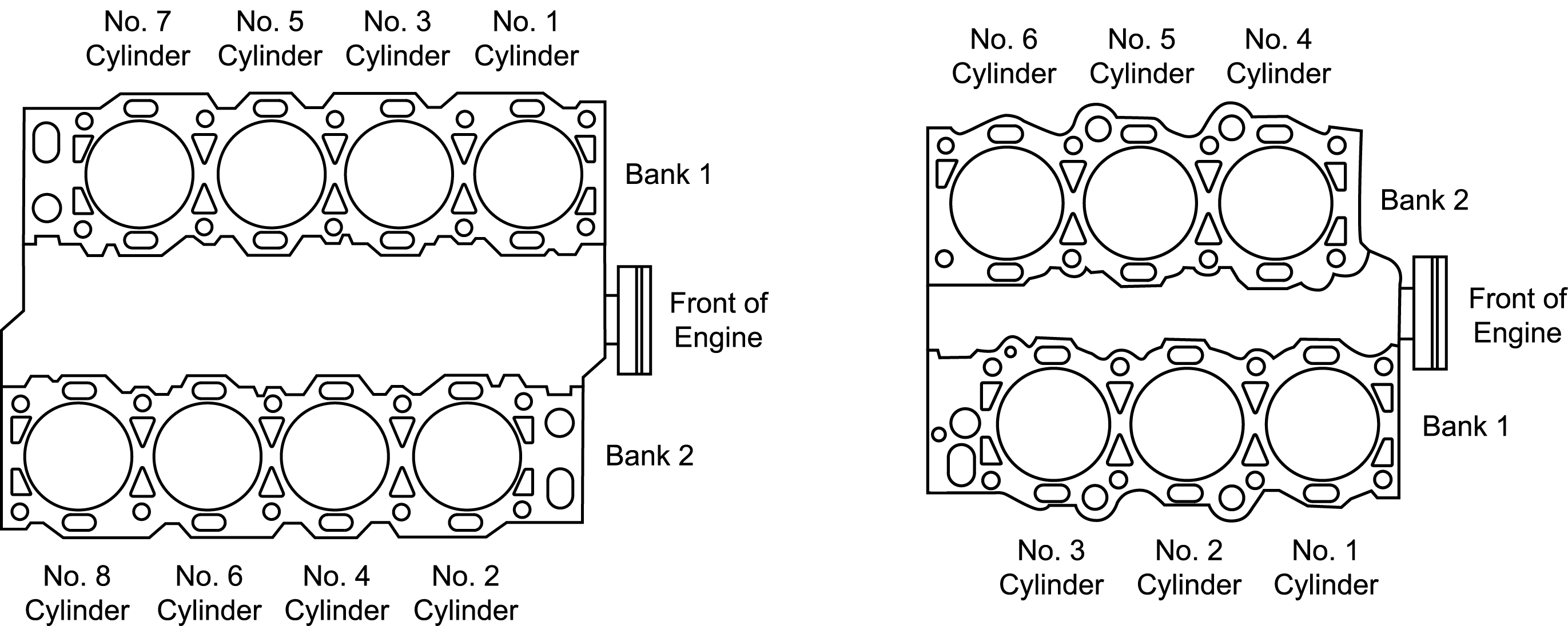
- Locate the sensor along the vehicles exhaust system and pre-treat the area with a spray lubricant. The use of a bay lift can greatly aide in this process. If you are replacing a sensor due to an ODBII code reference, you must know how to read the codes. B1S1, for example, refers to Bank 1, Sensor 1. To locate a specific engine bank, remember that Bank 1 will always be the most forward sensor bank on the engine block, as shown below:
 Sensor 1 will usually be in the upstream position and Sensor 2 the downstream. The illustration below shows typical sensor locations on common engine configurations. Regardless of the orientation of the engine in the vehicle, the left or right bank is determined by viewing from the rear of the engine (opposite the drive belts).
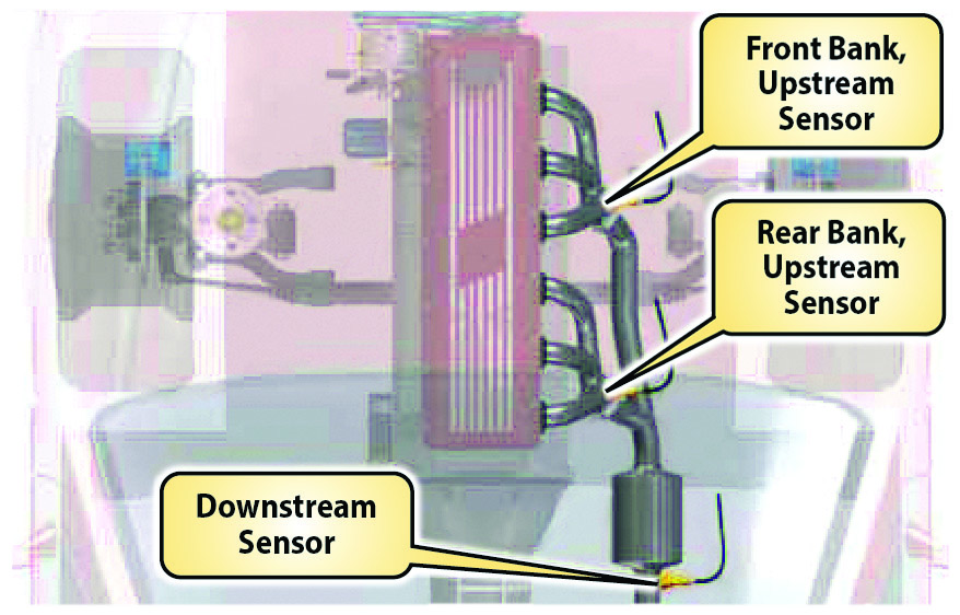
4 & 6 CYLINDER IN-LINE
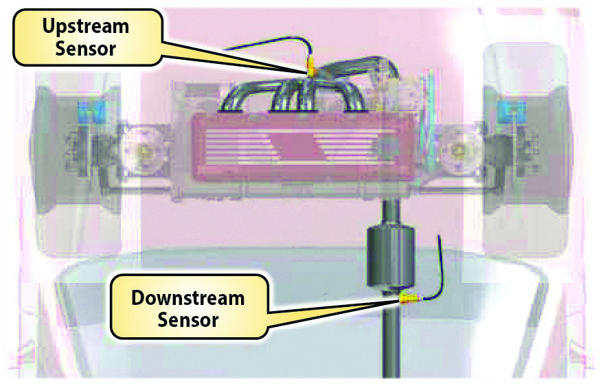
4 & 6 CYLINDER TRANSVERSE
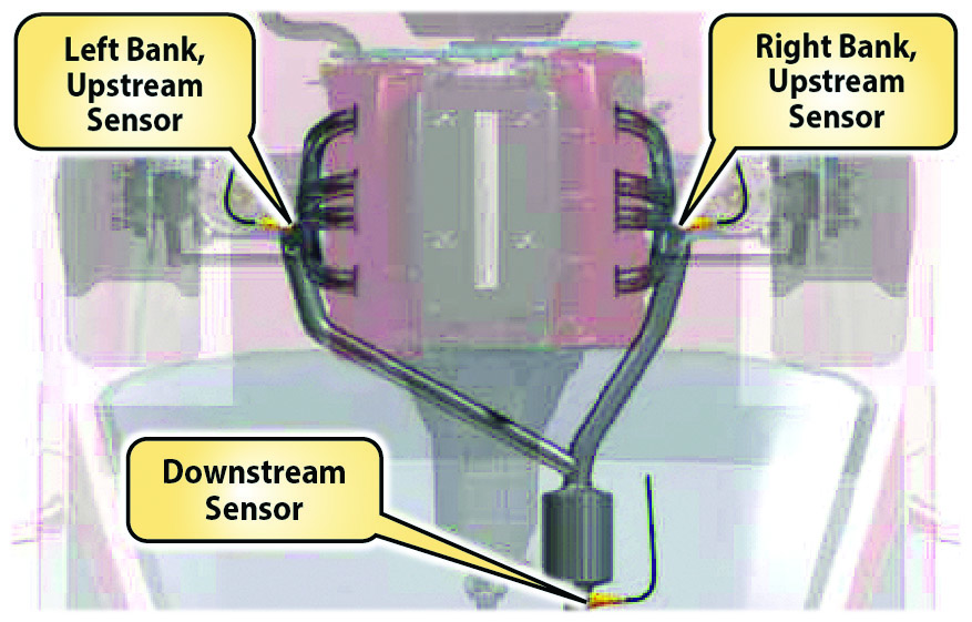 V8 CYLINDER IN-LINE
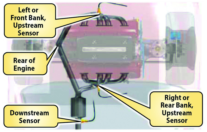 V8 CYLINDER TRANSVERSE
 - Remove the old sensor by first cutting away any zip ties that may be holding the unit in place. Then, unplug the connector. A small flat tip screwdriver may be helpful depressing the connector lock tab (FIGURE 1). Using your O2 socket, unscrew the existing sensor by turning it counterclockwise (FIGURE 2). Once the sensor has been loosened, you can finish removal by hand.

FIGURE 1
FIGURE 2 - Inspect the replacement sensor to be certain that it has the correct number of wires, and that the connector end is correct. Note that sensor types are not interchangeable; an A/F ratio sensor will not work in place of a regular O2 sensor, and etc. However, sensor styles are interchangeable. The replacement sensor may not look precisely as the old one did.
- Treat the threads of the new oxygen sensor by applying an even layer of anti-seize lubricant (FIGURE 3). Walker sensors include this component to insure a quality installation. Do not let the anti-seize come in contact with the head of the sensor.

FIGURE 3 - Start the new sensor in the bung by hand, and tighten to specifications (often 35 ft lbs) with a torque wrench. Do not over tighten the sensor (FIGURE 4).

FIGURE 4 - Connect the new sensor into the existing harness, making certain the connector halves line up properly (FIGURE 5). Finally, secure the sensor wire with a zip tie where necessary to avoid any chafes, snags, or burns. If the vehicle was producing a trouble code, make sure to clear it with a scanner (FIGURE 6).

FIGURE 5
FIGURE 6

