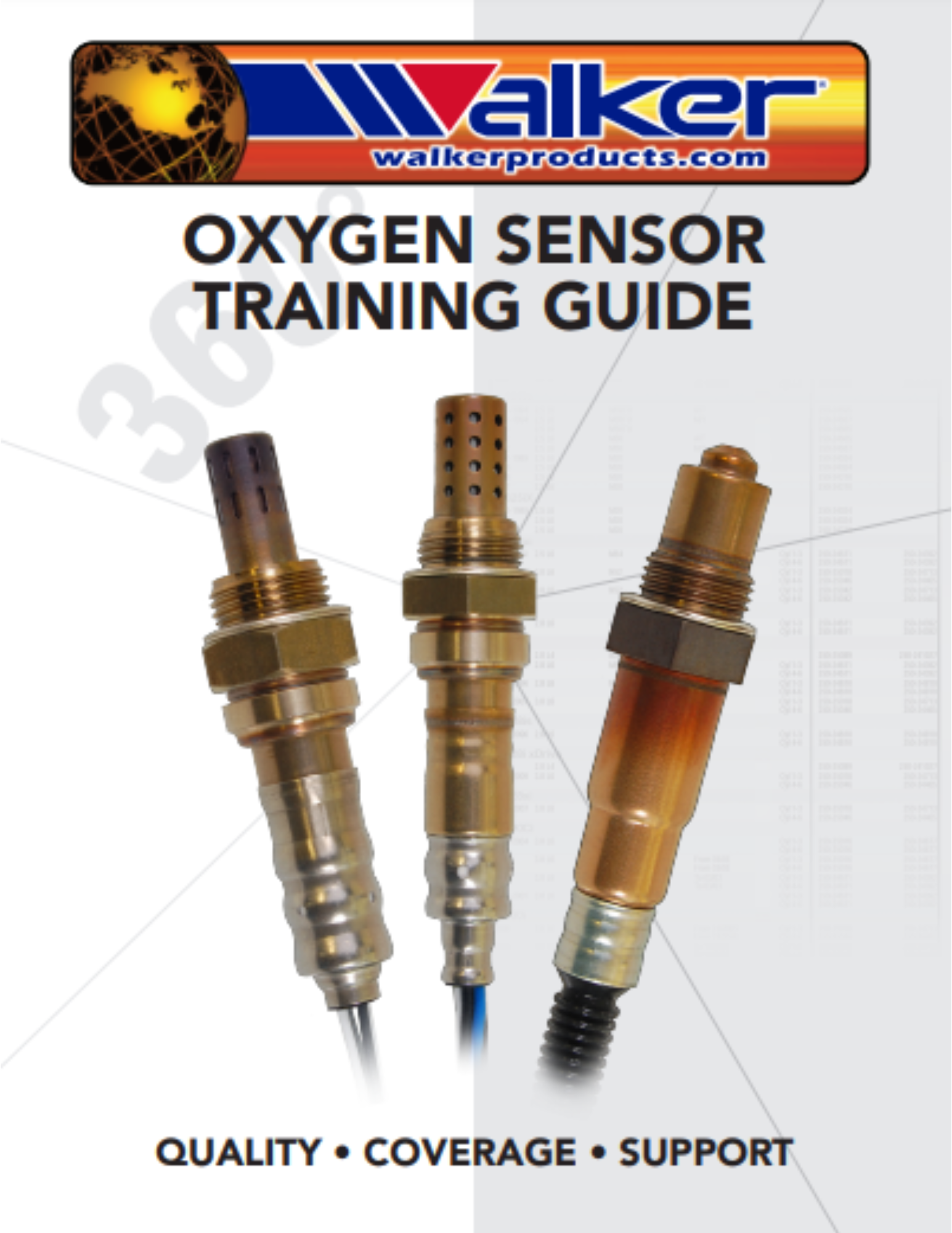
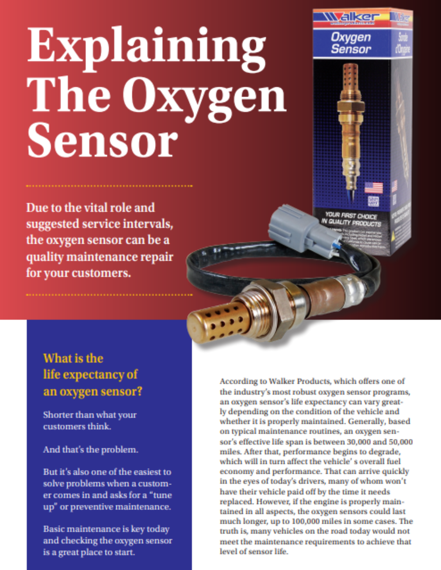
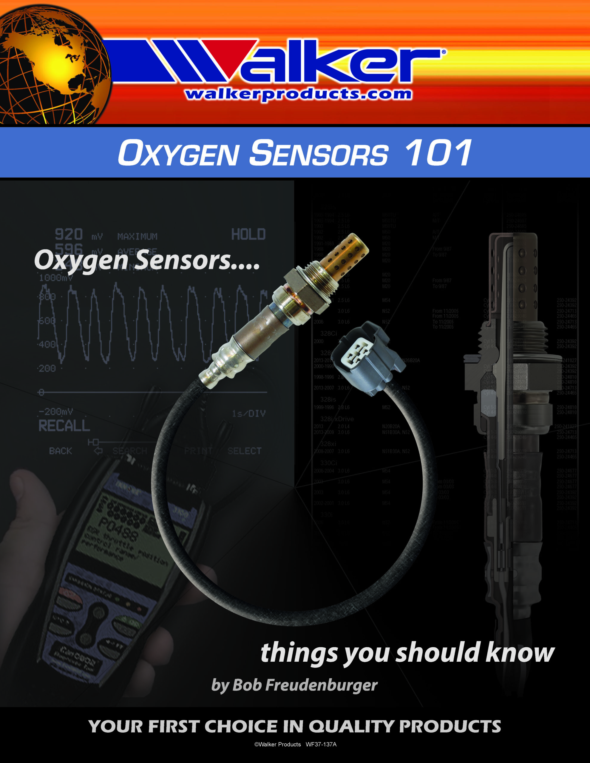
Automotive Oxygen Sensors (O2), Bung & Plug Kits
Click Here to find the right oxygen sensors for your vehicle
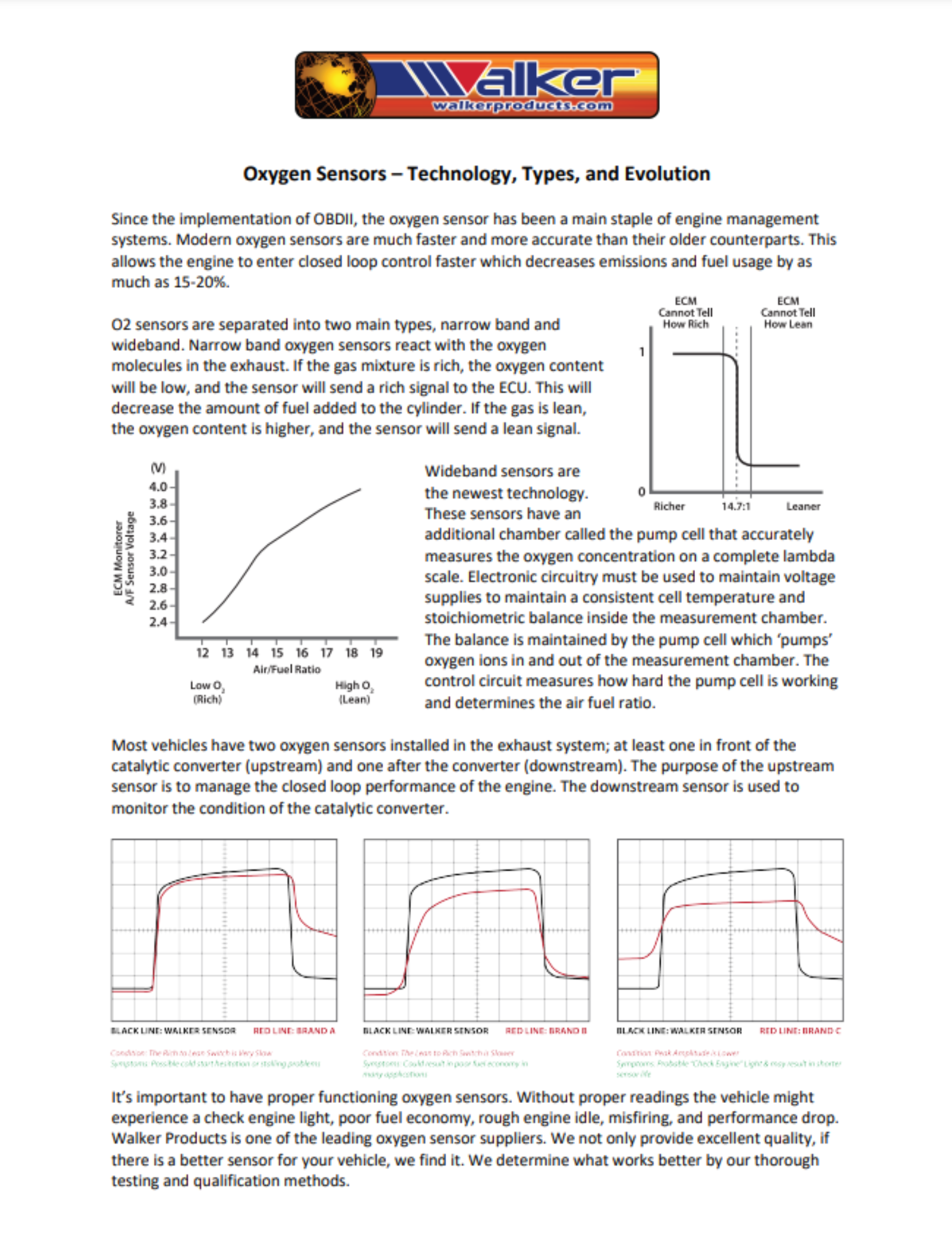
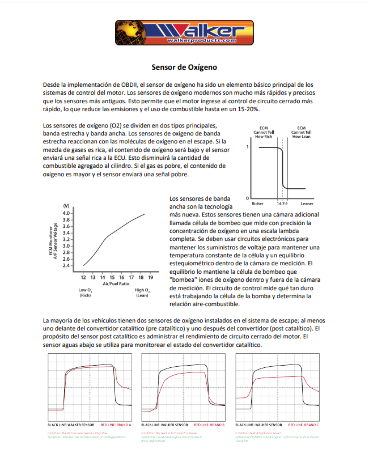
Located in the exhaust system, the oxygen sensor produces a voltage proportional to the amount of oxygen in the exhaust versus the air (<150 mV lean & >750 mV rich). This data is used to control the air-fuel mixture through PORT or TFI injectors and carburetors. Sensors are monitored or checked anywhere from 4 to 100 times per second. The air-fuel mixture is thus always moving from rich to lean averaging very close to stoichiometric (ideal) ratios.
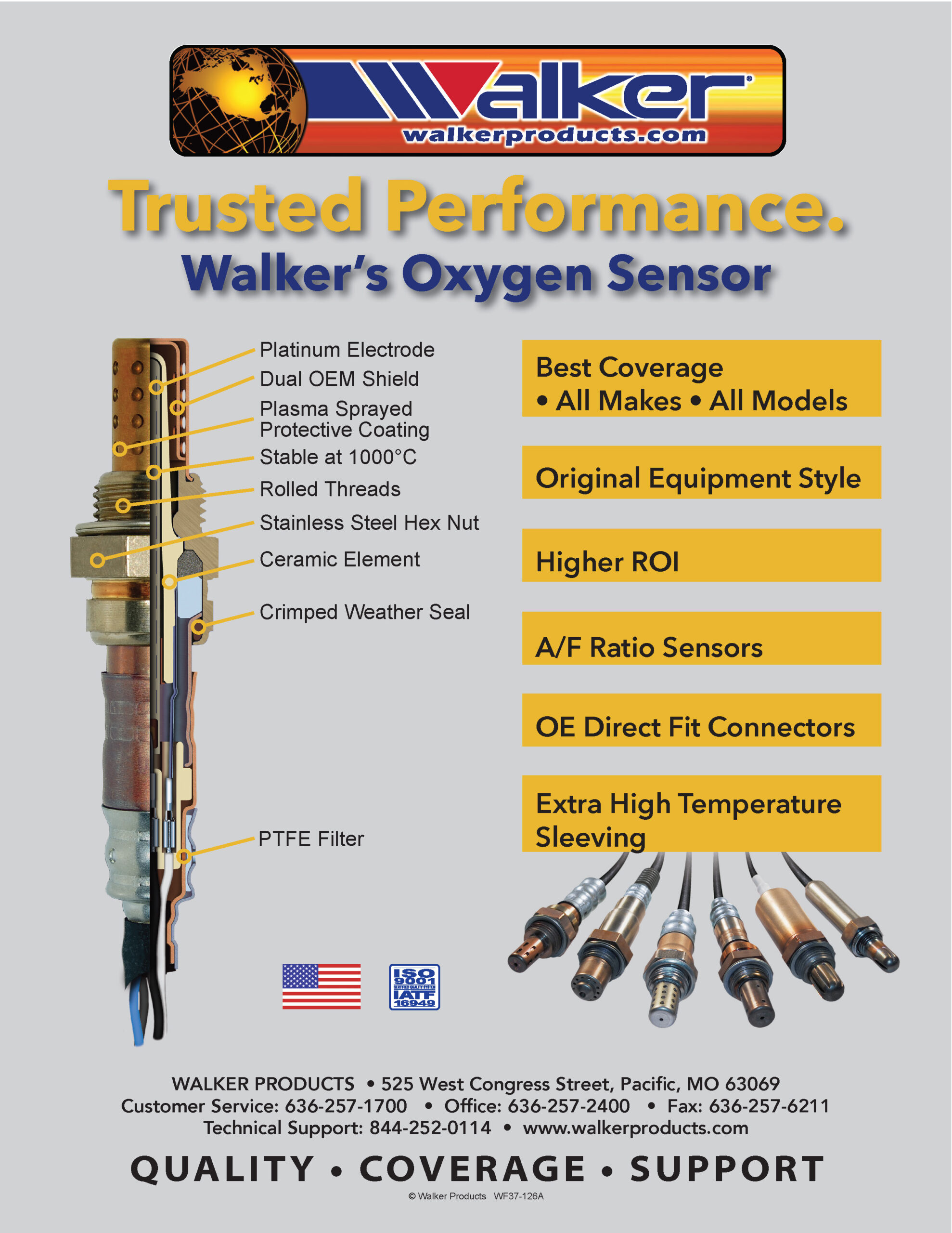
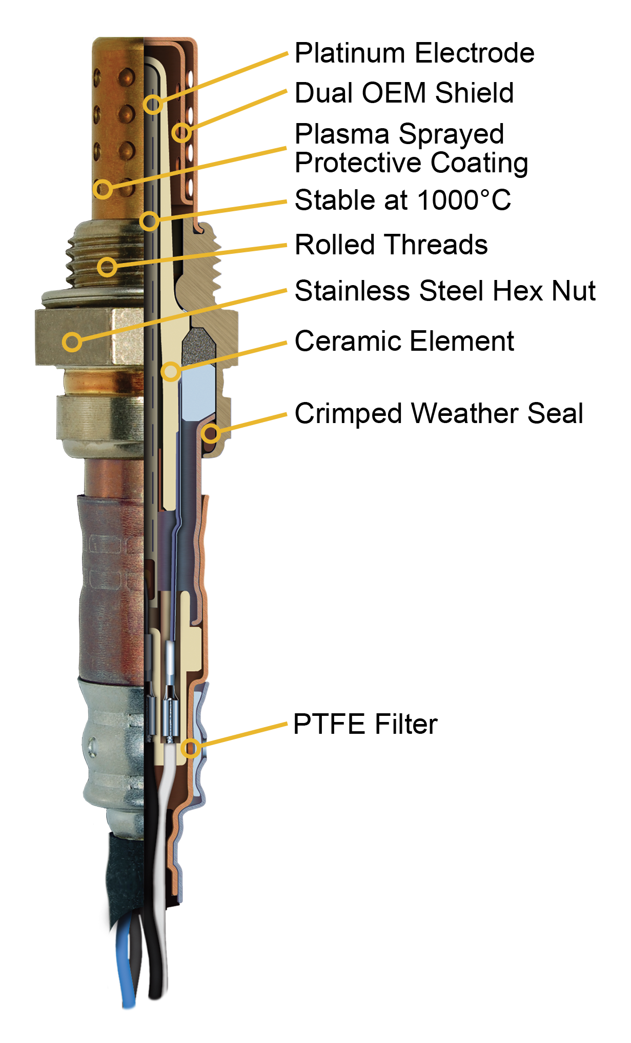
The ceramic sensor body is contained in a housing which protects it against mechanical effects and facilitates mounting. The ceramic body is made of stabilized zirconium dioxide (zirconia). Its surfaces are coated with electrodes made of a gas-permeable platinum layer. In addition, a porous ceramic coating has been applied to the side exposed to the exhaust gas. This coating prevents contamination and erosion of the electrode surfaces by combustion residue and particulates in the exhaust gases.
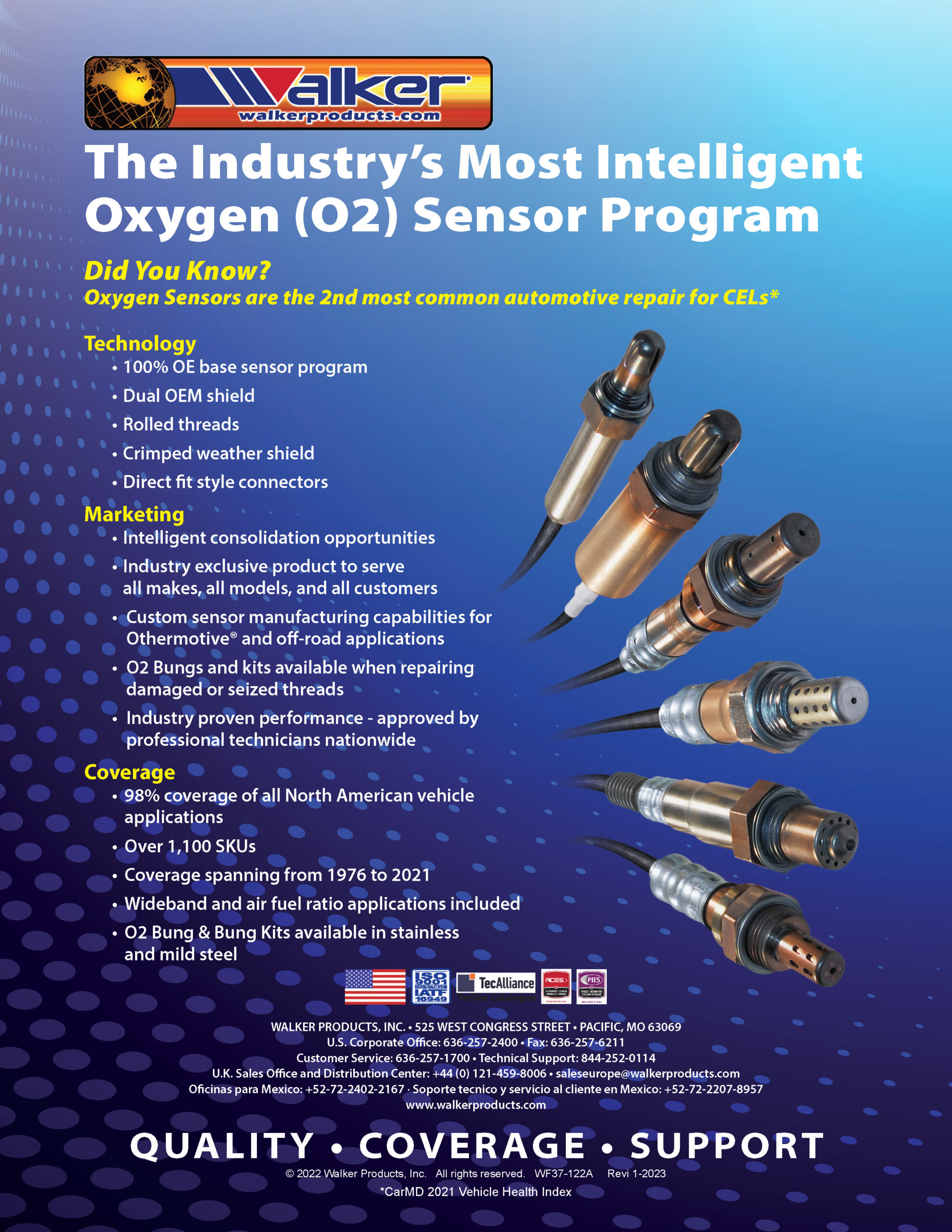
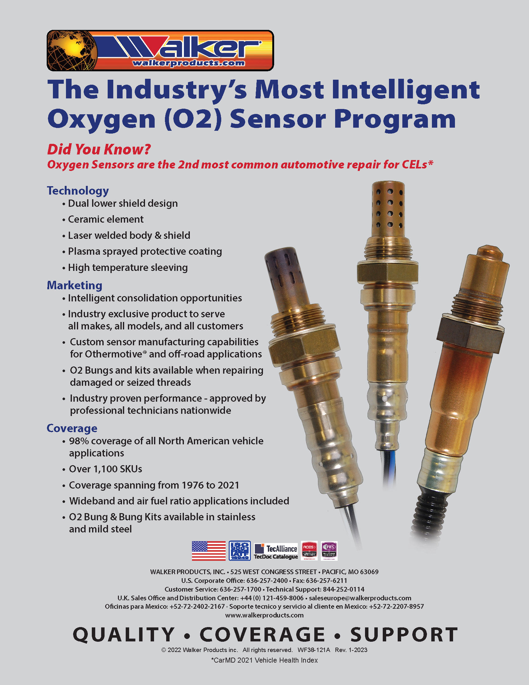
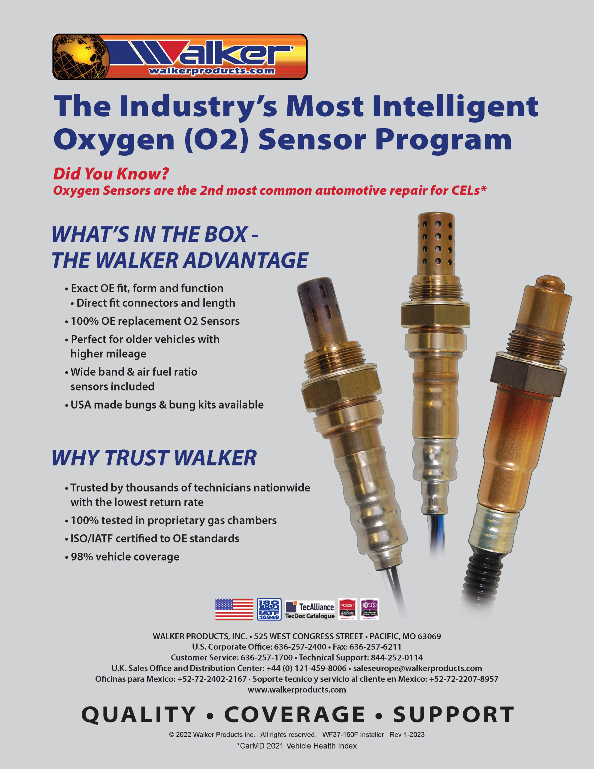
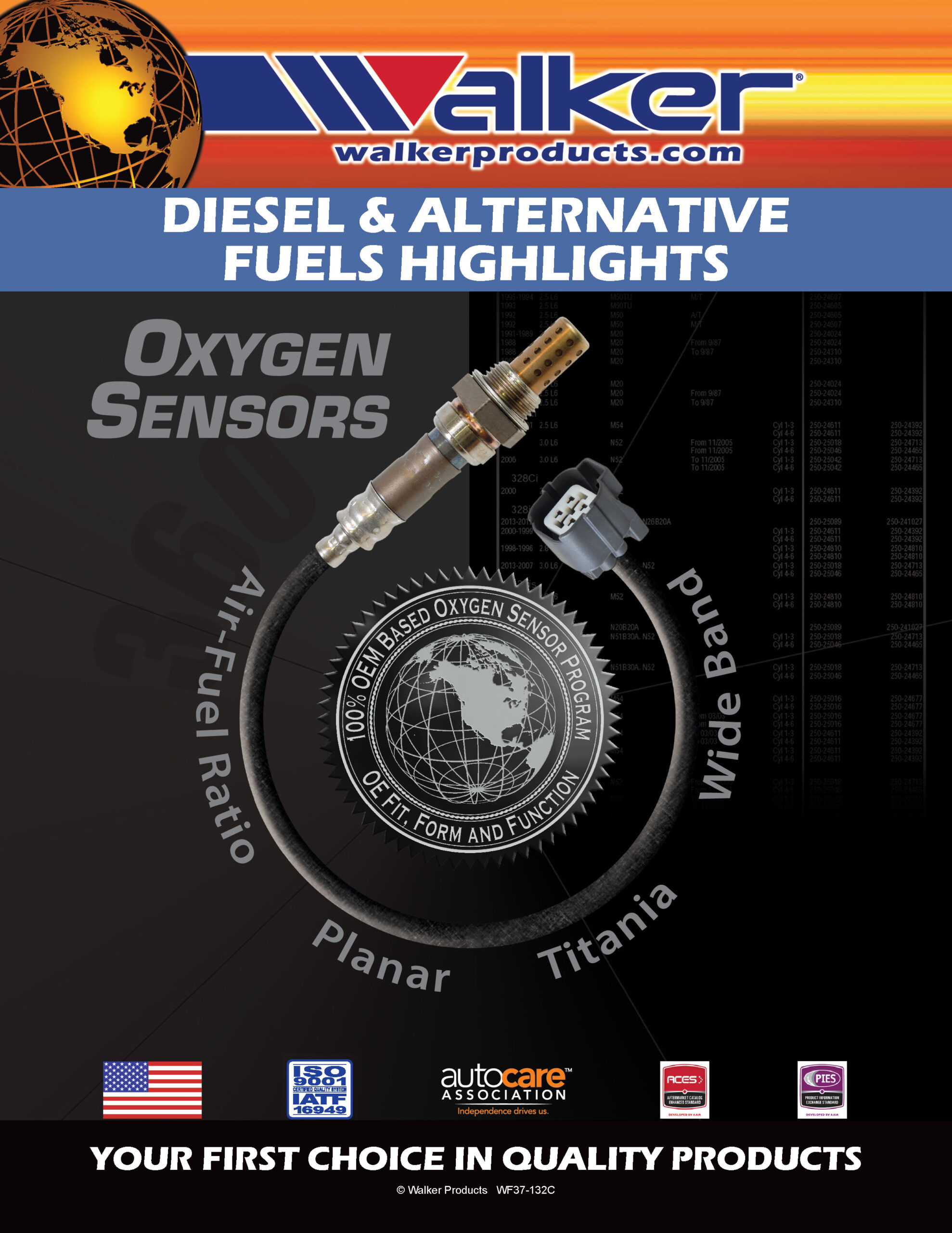
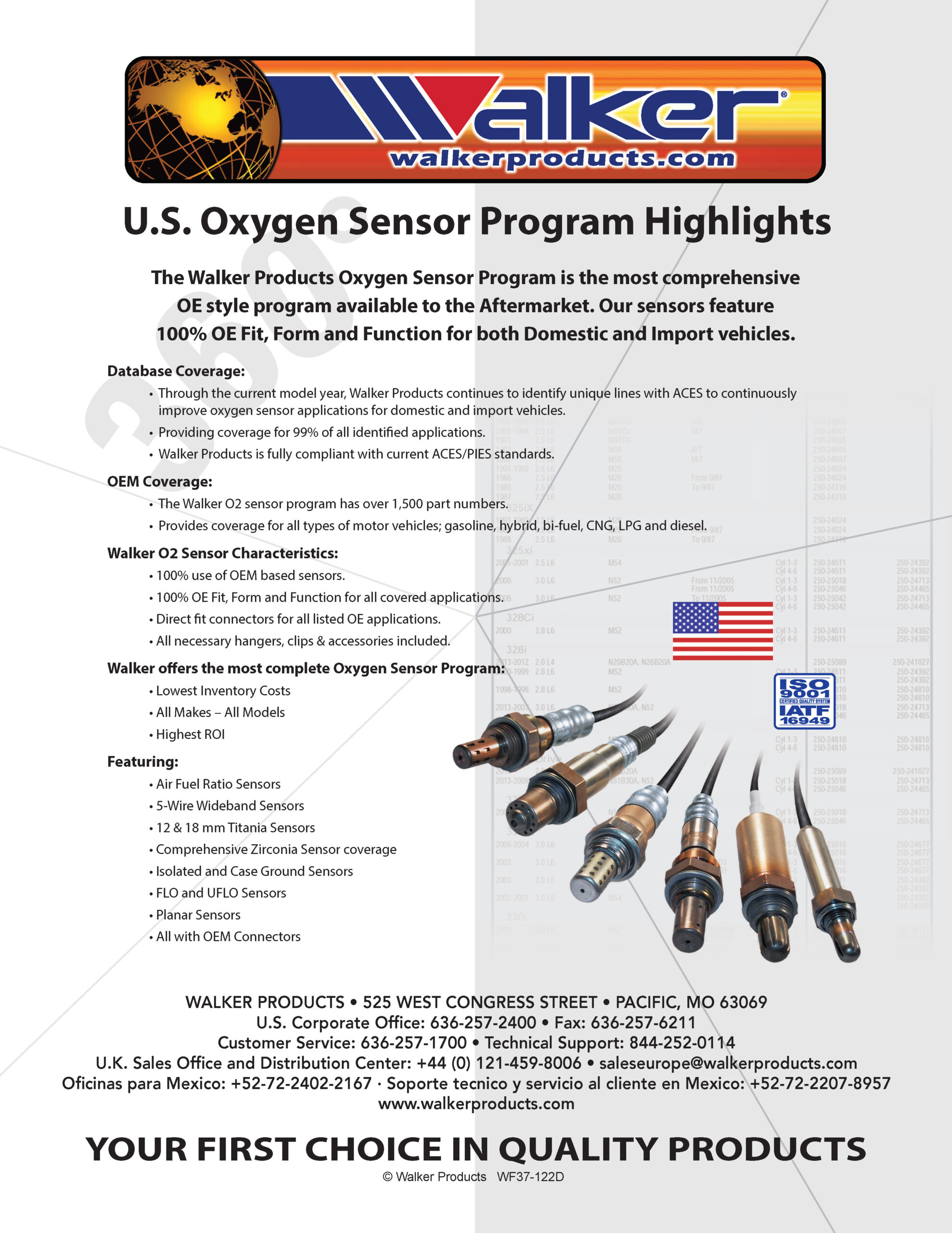
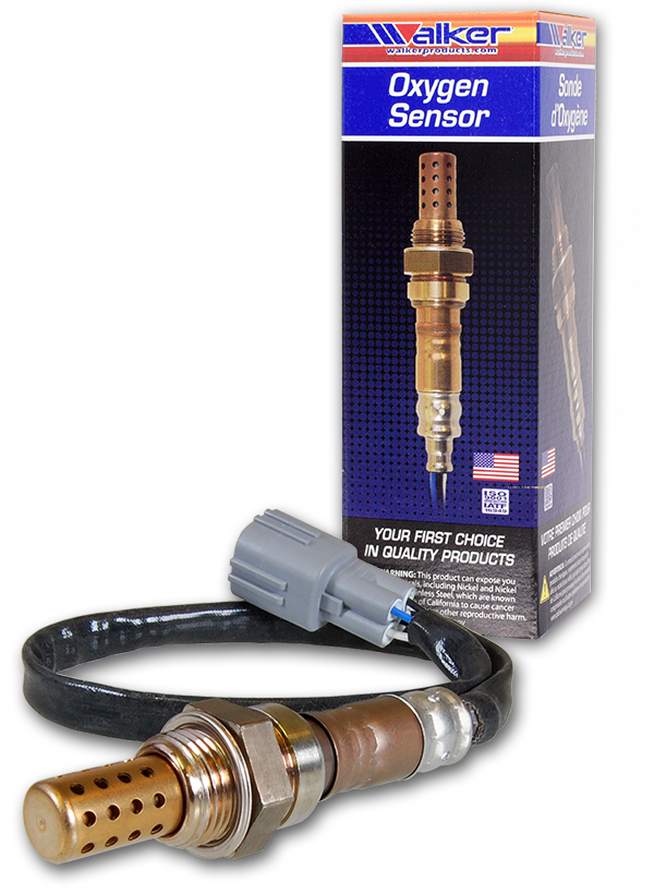
Walker Oxygen Sensors are precision made for outstanding performance and manufactured to meet and exceed all original equipment specification and test requirements.
- Improved Engine Response & Performance
- Lower Emissions
- Improved Fuel Economy
- Longer Sensor Life
- Meets OEM Specifications
Malfunctioning and Failed Sensors
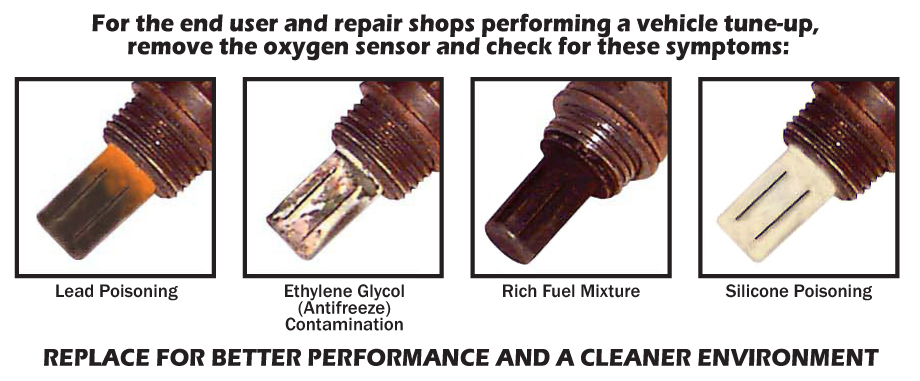
Oxygen sensors can fail when the sensor’s ceramic element is exposed to certain types of silicone compounds or when an oil-burning engine adds to the sensor becoming oil-fouled. Small amounts of tetra-ethyl lead in the gasoline or over-the-counter fuel additives, which are not “oxygen sensor safe,” can also kill an oxygen sensor.
Failures can occur instantaneously at the time the contaminant contacts the oxygen sensor, causing a dead sensor, or gradually over a period of time. Gradual deterioration results in a slow sensor which does not react as quickly as it should, causing the catalytic converter to perform less efficiently. This can lead to premature failure of the catalytic converter.
Slow oxygen sensors can cause a drop in fuel economy of 10-15%, excessive exhaust emissions, and poor drivability. Unfortunately, the symptoms of a slow oxygen sensor are not always obvious to the vehicle owner unless the vehicle fails an emissions test, a decline in fuel economy is noticed, or drivability problems occur.
Click here to diagnose types of oxygen sensor contamination.
A dead sensor can be detected with a relatively inexpensive digital volt-ohm meter. A slow sensor can only be diagnosed by using a digital oscilloscope or scope meter. Most installers will probably not be able to spot an oxygen sensor problem until it is too late and the catalytic converter is already well on its way to failure.
Preventive Maintenance
“Heated” type oxygen sensors have a built-in heater which heats the sensors. Much less exhaust gas is needed to contact the ceramic element, making these sensors less prone to contamination. “Heated” type sensors can also be located further downstream (closer to the catalytic converter) which increases their life expectancy. “Heated” type oxygen sensors should be checked or replaced every 60,000 to 100,000 miles.
Older technology one-wire and two-wire “unheated” type oxygen sensors should be checked or replaced every 30,000 to 50,000 miles. These sensors rely solely on hot exhaust gas to heat up to operating temperature and are designed to allow a large volume of exhaust gas to contact the active ceramic element. These sensors are exposed to contamination, especially the “wide-slot” varieties found on older Chrysler, Ford and General Motors vehicles.
Where are my oxygen sensors located?
Diagnostic Trouble Codes (DTC)
When oxygen sensor failure occurs, a DTC is recorded in the Engine Control Unit (ECU) and a Malfunction Indicator Lamp (MIL) is illuminated on the dash, alerting the driver the vehicle has a problem.
To diagnose the fault, a code reader or scan tool is connected to the vehicle to read the trouble code. The scan tools can vary in the display of information shown. Some show a definition for the code, while others show only a trouble code number. There are generic or standard OBD II codes and vehicle manufacturers who use additional codes called enhanced or OEM-specific codes. On many older (pre 1995) vehicles, a trouble code or DTC can be read without a scan tool or code reader by using a manual flash code procedure.
After having identified the description using a list of DTC trouble codes, the next step is to diagnose the fault. You must follow the diagnostic procedure to properly diagnose the system, sensor, and/or circuit.
The trouble code itself does not tell you which part to replace! The scan tools or code readers speak OBD II language, meaning the references to the engine are coded.
- B1 = Bank 1
- B2 = Bank 2
When applying OBD II to oxygen sensors, the codes would then read B1S1. This refers to Bank 1 Sensor 1.
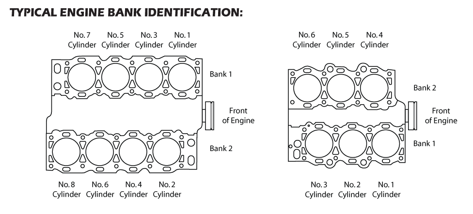
Finding Bank 1 is not difficult, but depends on the engine cylinder locations. For V6, V8, V10, V12, and W16 engines, whichever side cylinder #1 is on, is referred to as Bank 1. Bank 2 is the opposite side. For inline engines, there is only Bank 1, never a Bank 2.
Sensor 1 will be the pre catalytic position and Sensor 2 would typically be the post catalytic position. In some instances, Sensor 2 can be pre catalytic thus making Sensor 3 post catalytic.
View Oxygen Sensor Locations
Oxygen Sensor FAQ
Life Expectancy of an Oxygen Sensor
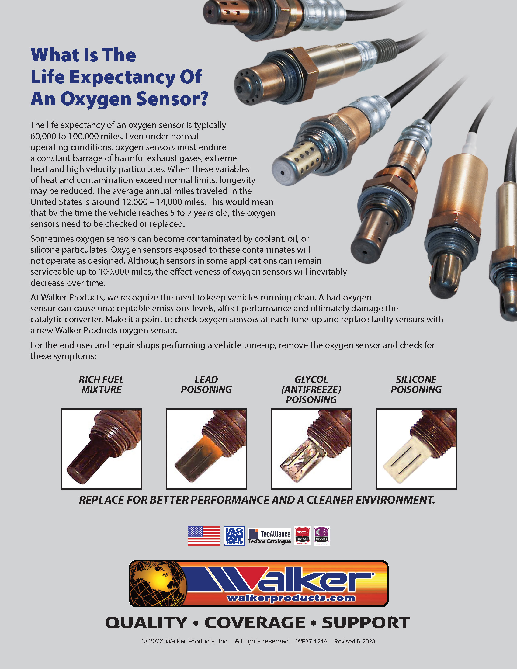
The life expectancy of an oxygen sensor is typically 60,000 to 100,000 miles. Even under normal operating conditions, oxygen sensors must endure a constant barrage of harmful exhaust gases, extreme heat and high velocity particulates. When these variables of heat and contamination exceed normal limits, longevity may be reduced. The average annual miles traveled in the United States is around 12,000 – 14,000 miles. This would mean that by the time the vehicle reaches 5 to 7 years old, the oxygen sensors need to be checked or replaced.
Sometimes oxygen sensors can become contaminated by coolant, oil, or silicone particulates. Oxygen sensors exposed to these contaminates will not operate as designed. Although sensors in some applications can remain serviceable up to 100,000 miles, the effectiveness of oxygen sensors will inevitably decrease over time.
At Walker Products, we recognize the need to keep vehicles running clean. A bad oxygen sensor can cause unacceptable emissions levels, affect performance and ultimately damage the catalytic converter. Make it a point to check oxygen sensors at each tune- up and replace faulty sensors with a new Walker oxygen sensor.
We also have an extensive selection of exhaust Bungs & Plugs available in both Mild Steel and Stainless Steel. Our exhaust Bungs & Plugs are made in house at our Screw Machine Facility in Fruita, Colorado USA. We offer these individually, in standard or custom stocking kits, and in bulk. We also offer Custom Bungs & Plugs for any of your exhaust or special needs.
In addition, we have a large assortment of O2 Sensor Sockets and Wrenches, giving the technician or DIY’er the right tools needed to complete any O2 Sensor project with ease and accessibility.
6.0 COMMON OBDII CODES
When an O2 sensor failure occurs, a DTC or diagnostic trouble code is recorded in the ECU and a check engine light appears on the vehicle’s dash. The DTC must be retrieved using a scanning tool. There are generic or standard OBDII codes along with enhanced or OEM specific codes. Below is a list of the more common OBDII codes, along with the possible cause or causes of the code.
| Code | Description | Location | Possible Causes |
|---|---|---|---|
| P0150 | O2 Sensor Circuit Malfunction | Bank 2 Sensor 1 | Broken sensor element. Sensor disconnected. Shorted wiring. Catastrophic failure of sensor due to thermal shock. |
| P0151 | O2 Sensor Circuit Low Voltage | Bank 2 Sensor 1 | Short in wiring between sensor ground and signal wire. Silicone or ethylene glycol poisoning of the air reference electrode. |
| P0152 | O2 Sensor Circuit High Voltage | Bank 2 Sensor 1 | Short in wiring between heater circuit and signal wire. Sensor immersed in water. Silicone or ethylene glycol poisoning of the sensing electrode. |
| P0153 | O2 Sensor Circuit Slow Response | Bank 2 Sensor 1 | Sensor electrode protective coated with carbon. Silicone poisoning. Ethylene glycol poisoning. Failed sensor heater. Heater circuit fuse. |
| P0154 | O2 Sensor Circuit No Activity Detected | Bank 2 Sensor 1 | Short in wiring between sensor ground and signal wire. Silicone or ethylene glycol poisoning of the air reference electrode. |
| P0155 | O2 Sensor Heater Circuit Malfunction | Bank 2 Sensor 1 | Sensor heater shorted or open. Replacement sensor installed with incorrect heater current values. Open or shorted electrical connections. Heater circuit fuse. |
| P0156 | O2 Sensor Circuit Sensor Malfunction | Bank 2 Sensor 2 | Broken sensor element. Sensor disconnected. Shorted wiring. Catastrophic failure of sensor due to thermal shock. |
| P0157 | O2 Sensor Circuit Low Voltage | Bank 2 Sensor 2 | Short in wiring between sensor ground and signal wire. Silicone or ethylene glycol poisoning of the air reference electrode. |
| P0158 | O2 Sensor Circuit High Voltage | Bank 2 Sensor 2 | Short in wiring between heater circuit and signal wire. Sensor immersed in water. Silicone or ethylene glycol poisoning of the sensing electrode. |
| P0159 | O2 Sensor Circuit Slow Response | Bank 2 Sensor 2 | Sensor electrode protective coated with carbon. Silicone poisoning. Ethylene glycol poisoning. Failed sensor heater. Heater circuit fuse. |
| P0160 | O2 Sensor Circuit No Activity Detected | Bank 2 Sensor 2 | Short in wiring between sensor ground and signal wire. Silicone or ethylene glycol poisoning of the air reference electrode. |
| P0161 | O2 Sensor Heater Circuit Malfunction | Bank 2 Sensor 2 | Sensor heater shorted or open. Replacement sensor installed with incorrect heater current values. Open or shorted electrical connections. Heater circuit fuse. |
| P0162 | O2 Sensor Circuit Malfunction | Bank 2 Sensor 3 | Broken sensor element. Sensor disconnected. Shorted wiring. Catastrophic failure of sensor due to thermal shock. |
| P0163 | O2 Sensor Circuit Low Voltage | Bank 2 Sensor 3 | Short in wiring between sensor ground and signal wire. Silicone or ethylene glycol poisoning of the air reference electrode. |
| P0164 | O2 Sensor Circuit High Voltage | Bank 2 Sensor 3 | Short in wiring between heater circuit and signal wire. Sensor immersed in water. Silicone or ethylene glycol poisoning of the sensing electrode. |
| P0165 | O2 Sensor Circuit Slow Response | Bank 2 Sensor 3 | Sensor electrode protective coated with carbon. Silicone poisoning. Ethylene glycol poisoning. Failed sensor heater. Heater circuit fuse. |
| P0166 | O2 Sensor Circuit No Activity Detected | Bank 2 Sensor 3 | Short in wiring between sensor ground and signal wire. Silicone or ethylene glycol poisoning of the air reference electrode. |
| P0167 | O2 Sensor Heater Circuit Malfunction | Bank 2 Sensor 3 | Sensor heater shorted or open. Replacement sensor installed with incorrect heater current values. Open or shorted electrical connections. Heater circuit fuse. |
| P0170 | Fuel Trim Malfunction | Bank 1 | Vacuum Leak. Gas in engine oil. Air leaks. Bad O2 Sensor. |
| P0171 | System Too Lean | Bank 1 | Leaking exhaust gasket or vacuum lines. Defective fuel injector(s). Damaged fuel pump. Clogged fuel filter. |
| P0172 | System Too Rich | Bank 1 | Vacuum leak. Fuel pressure or delivery problem. Faulty MAF sensor. |
| P0173 | Fuel Trim Malfunction | Bank 2 | Vacuum Leak. Gas in engine oil. Air leaks. Bad O2 Sensor. |
| P0174 | System Too Lean | Bank 2 | Leaking exhaust gasket or vacuum lines. Defective fuel injector(s). Damaged fuel pump. Clogged fuel filter. |
| P0175 | System Too Rich | Bank 2 | Vacuum Leak. Gas in engine oil. Air leaks. Bad O2 Sensor. |


